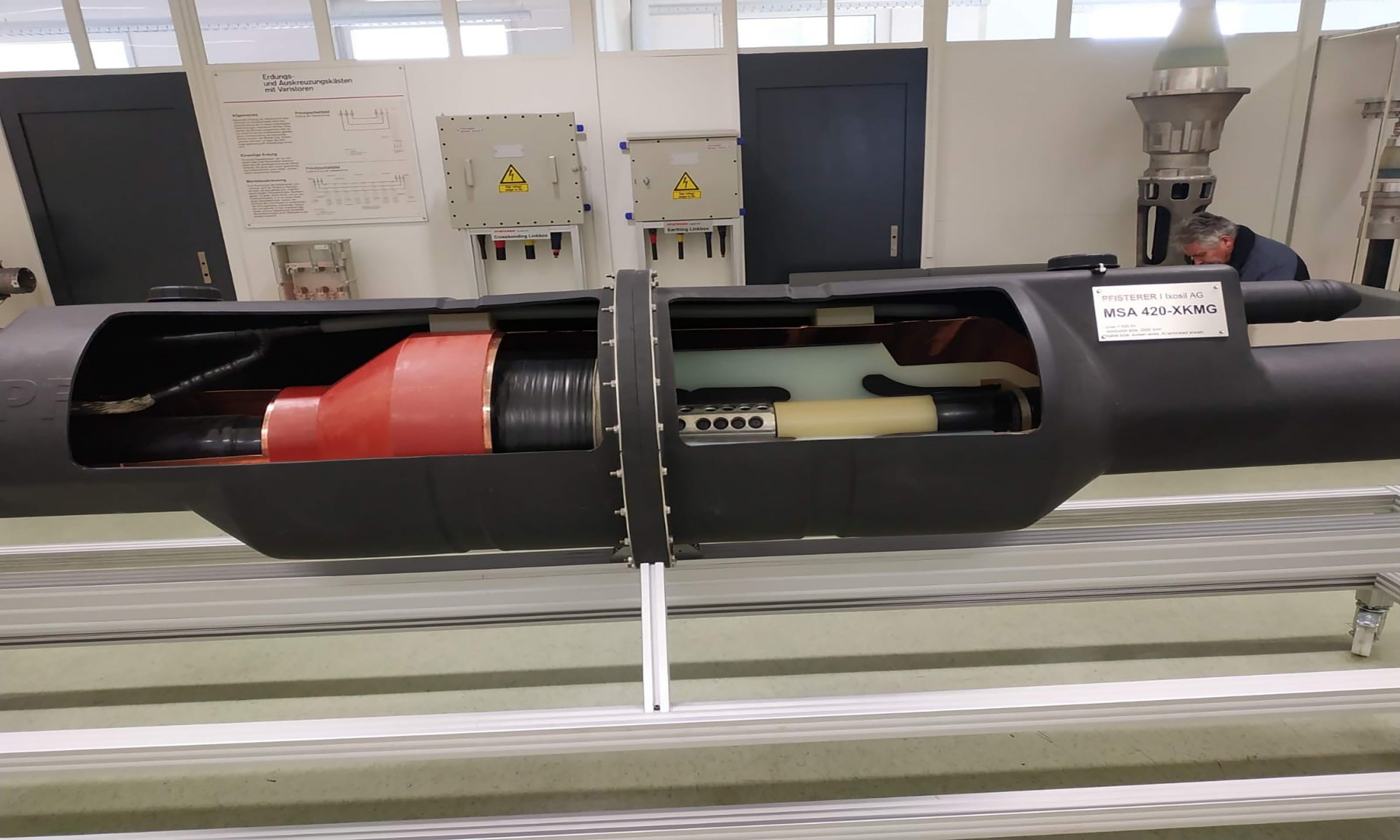
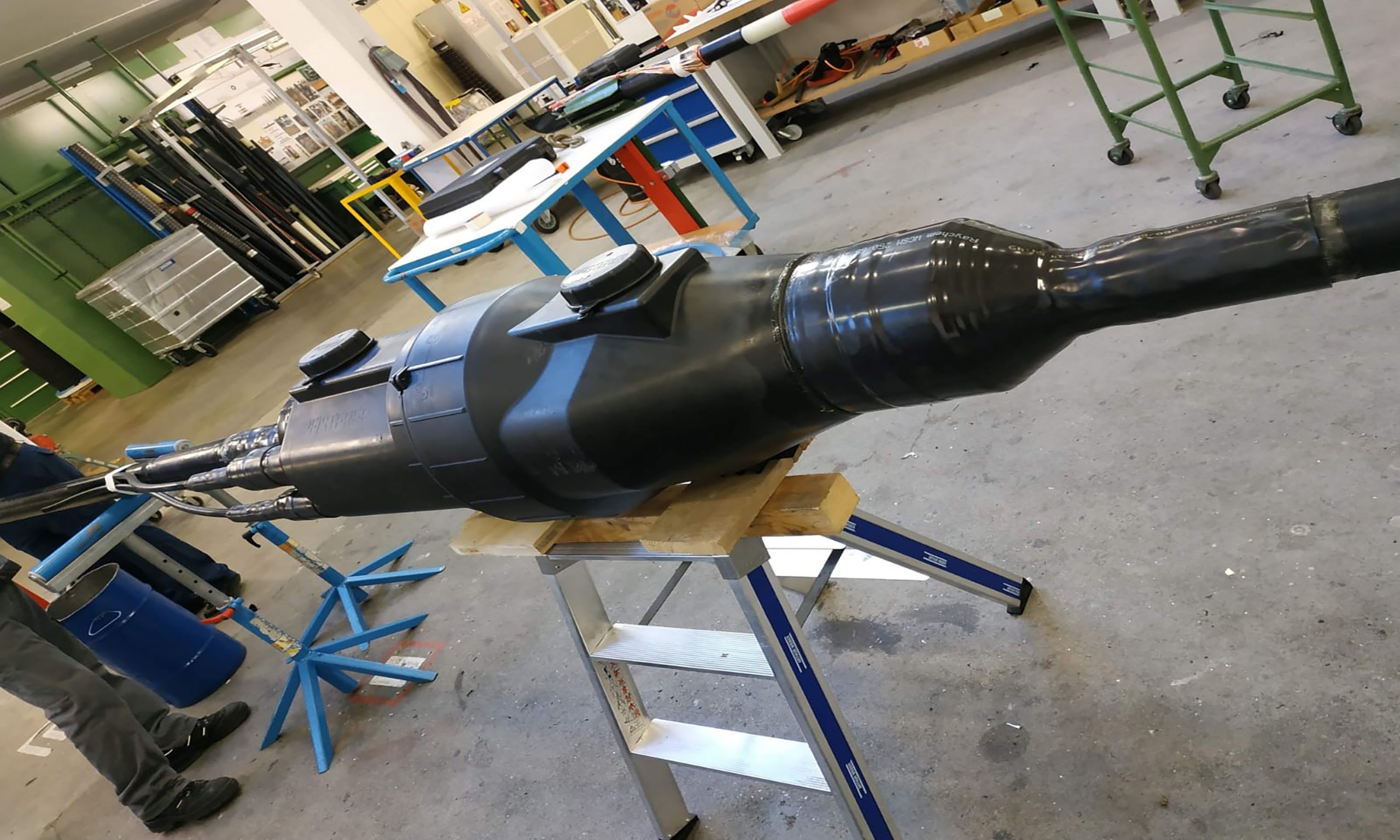
EHV Cable Joint

The conductor shield member is constructed to be pre-curled so as to speed the assembly of the joint.
Straight through Jointing Procedure
Straight through joint mainly two types according to cable sheath jointing:
-
NJ- Normal Joint, where cable sheath connection is as usual, not insulated through link-box;
-
IJ- Insulated Joint, where cable sheath connection is as insulated through link -ox.
There are about four commonly used types of joints that differ in mechanical arrangement and location where at used.
Straight through Jointing Procedure
Straight through joint mainly two types according to cable sheath jointing:
- NJ- Normal Joint, where cable sheath connection is as usual, not insulated through link-box;
- IJ- Insulated Joint, where cable sheath connection is as insulated through link -ox.
There are about four commonly used types of joints that differ in mechanical arrangement and location where at used.
- Straight through joint
- T or Y branch joint
- Pot end joint
Each cable is to be run in one continuous length except where the run of cable exceeds the normal manufactured lengths. No other straight joints will be permitted unless specifically authorized by the Engineer.
The outer sheath of all joints buried in the ground shall be contained in a glass fiber or similar box filled with compound or other approved method. The XLPE cable is provided with sectionalization on the sheaths on every sixth joint or 3 km whichever is less, with links and earthing provided for the earth screen. Normal operation will be with the sheath bonding links closed and the earth link open.
All XLPE joints and terminations shall be carried out under strictly controlled conditions by cable jointers for the XLPE cable manufacture. The joint insulation shall be of the vulcanized type or other approved type. The installation rates of the joints specified in schedule IV are to include allowance for the complete joint bay installation including excavation civil work jointing earthing and ancillary equipment.
Where the armour wires of plastic insulated cables constitute the earthed metallic shield such wires shall be efficiently bonded across the joint in a approved manner. The electrical resistance of such bonds shall not exceed that of an equal length of the cable armour wires. Suitable care shall be taken to ensure that the bond contacts do not deteriorate in service.
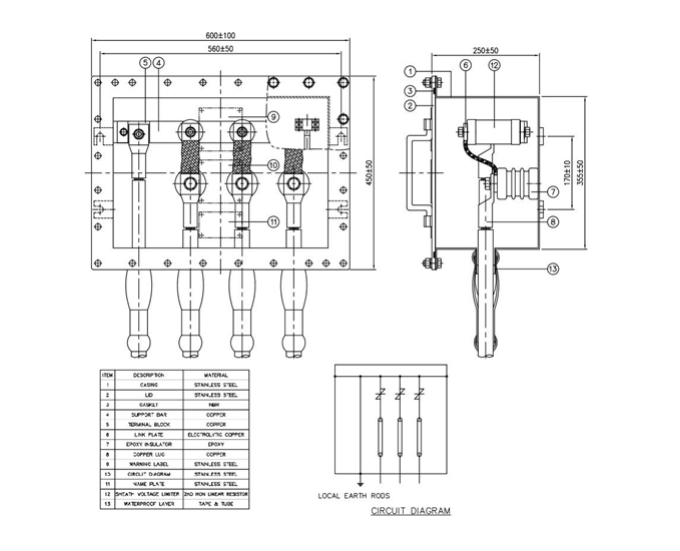
Bonding and Earthing Procedure: Bonding and earthing connection formation arranged in earthing link box. The application of link box is as below:
-
Direct grounding
-
Single point bonding
-
Cross bonding
-
Cross bonding and transposition
-
Sheath voltage limiters (SVL)
-
Earthing link box formation may be following five types:
1. Link Box for earthing in 1-1 way;
2. Link Box for earthing in 3-1 way ;
3. Link box for earthing in 3-1 way with cross bonding;
4. Link box for earthing in 3-1 way with SVL (sheath votage limiter);
5. Link Box for earthing in 3-1 way for joint bay earthing.


